ZRP X3 Big Brake Kit Install Instructions
This install is complex and takes 4-6 hours, if you are not comfortable with it, we recommend having a dealer or race shop install.
*This kit ships with an aggressive pad designed for high temperature ranges. Failure to get pads up to temp may result in premature wear of the pads and rotors. If you are not using this kit in a race application please contact us prior to purchasing so we can accommodate your setup.
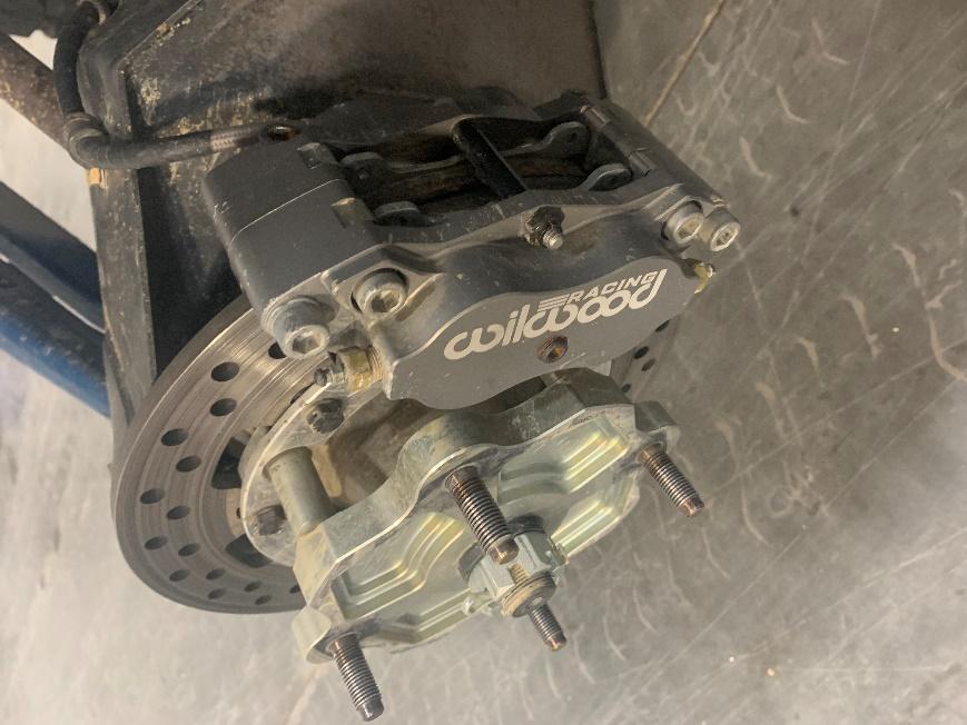
Parts Included in Kit
Installing The Master Cylinder
-
Remove the stock master cylinder and stock brake lines.
-
The fittings and plugs are LOOSELY installed in the right configuration, you will need to Loctite and tighten them.
-
You will need to install the custom pushrod, We recommend putting grease on the pushrod and hole and using the dust seal, this will need be installed after the master is mounted. You will reuse the stock clevis and jam nut to attach to the pedal, you will need to adjust to the proper position once install is complete
-
Install the master cylinder with the mounting holes horizontal and reservoir mounts upwards. You will need to drill 2 holes in the mounting plate. Utilize the 2 shorter socket head cap screws and flanged lock nuts to attach to plate
-
Install the reservoir connection caps that are supplied and ensure you use the supplied o-rings and connect to either the OEM reservoirs or mount the supplied Wilwood ones. We recommend using the wildwood ones due to larger capacity

-
Properly Installed Master Cylinder
Installing Rotors and Calipers
-
Remove the stock caliper, hub and stock rotor from the hub
-
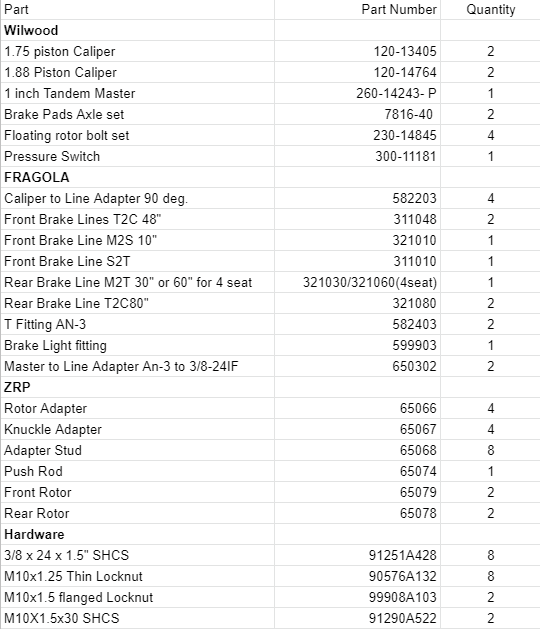
Install the rotor to the adapter with the floating bolt hardware, the hex size of the bolt should be on the side on the adapter with the ZRP Logo, The floating “Hat” nut should fit in the machine slots on the rotor on the opposite side. We recommend red Loctite and wire tying these bolts. Torque them to 220 Inch-Pounds

Properly Assembled Floating Rotor
-
Install the rotor adapter to the hub per Can-Am’s Specs.
-
Install the knuckle adapter to the knuckle with the studs pointing towards the inside of the vehicle, using the supplied thin locknuts, Torque them to 55 ft-lbs, we recommend blue Loctite as well. The ones labeled “X3” are for the rear. The ones labeled “X3 R” and “X3 L” are for the front respectively.
-
Install hub per Can-Am’s specs
-
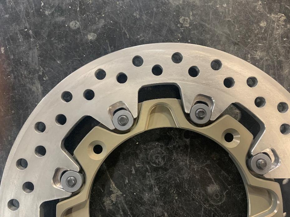
Install the caliper, using the supplied socket head cap screws. torque the bolts to 30-35 ft-lb and use blue Loctite.

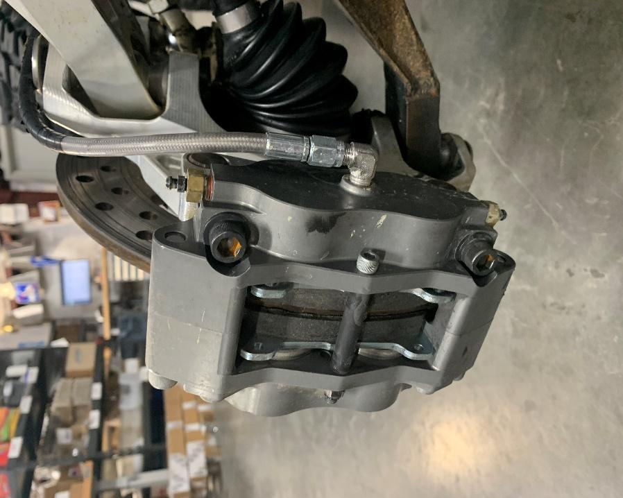
Properly Installed Front Caliper

Properly Installed Rear caliper
Installing Brake lines
-
All Brake lines are stainless steel braided lines with AN-3 fittings and all fittings should be torqued to 95-140 Inch-Pounds and checked to make sure they do not leak..
-
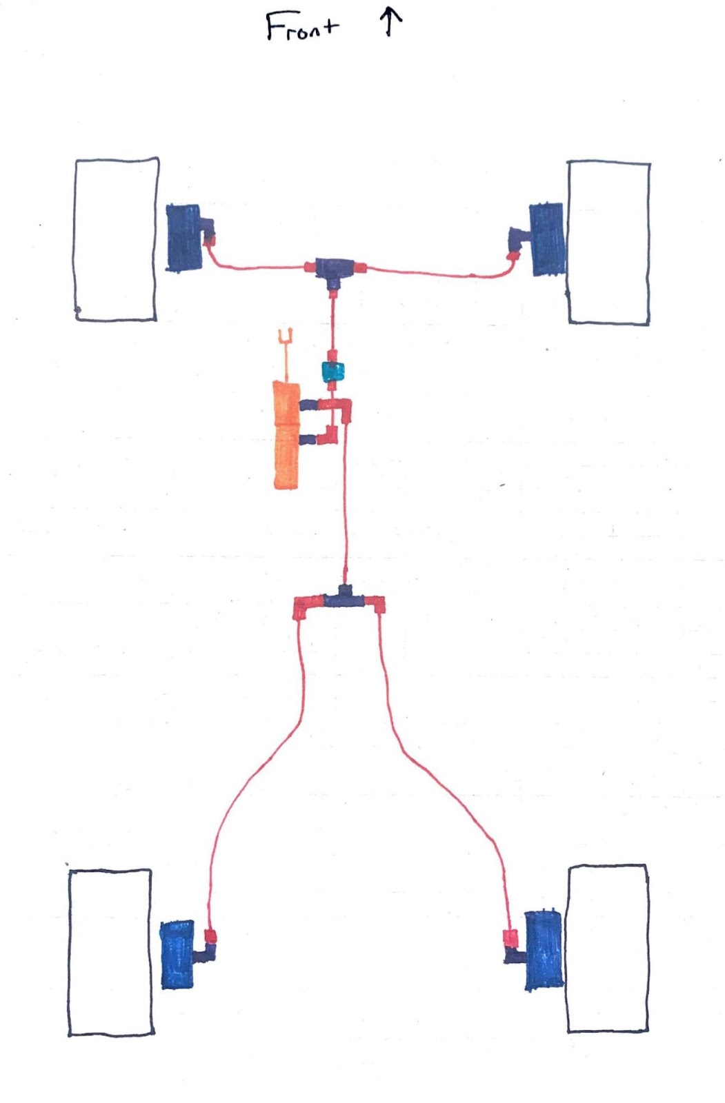
Use the attached Diagram and instructions to install in the right configuration
-
It is your responsibility to adequately fasten and shield brake lines and ensure there are no pinch points than could damage lines.
-
Front Brake lines will go in the order as follows, Starting at the master
-
Master Cylinder, using the port closest to the driver
-
321010 with 90 on the master side
-
Brake Light fitting, 599903
-
311010
-
T fitting, 582403
-
311048
-
90 fitting, 582203
-
Caliper
-
Rear Brake Line will go in the order as follows
-
Master Cylinder, Using port closest to front of vehicle
-
321030 with 90 on master side
-
T fitting, 582403
-
321080 with 90 on the T side
-
90 fitting, 582203
-
Caliper
Final Assembly Notes
-
You will need to wire the supplied pressure switch into the stock pressure switch harness for Brake lights to work.
-
You will need to fully prime and bleed the system, This can be a lengthy process as the entire system will start with no fluid in it.
-
Verify the lines going into the master are as pictured in reference picture 1, with the front lines going in to the rear most master cylinder port and the rear lines into the front most port. This is critical for proper bias.
-
The rotors may not initially “float” by hand but will wear in and float properly within the first few miles.